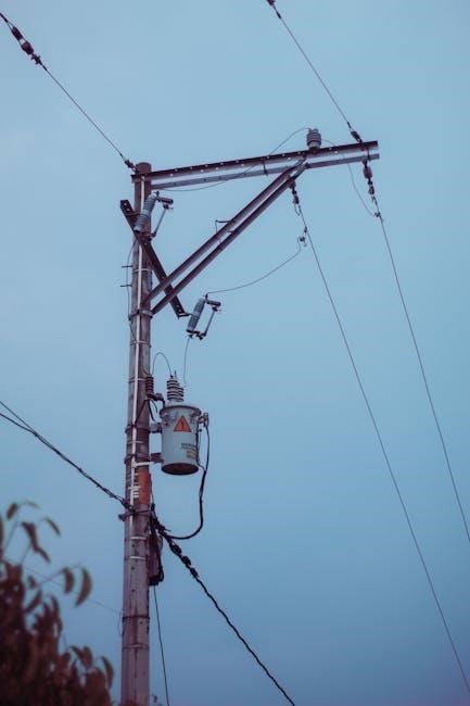
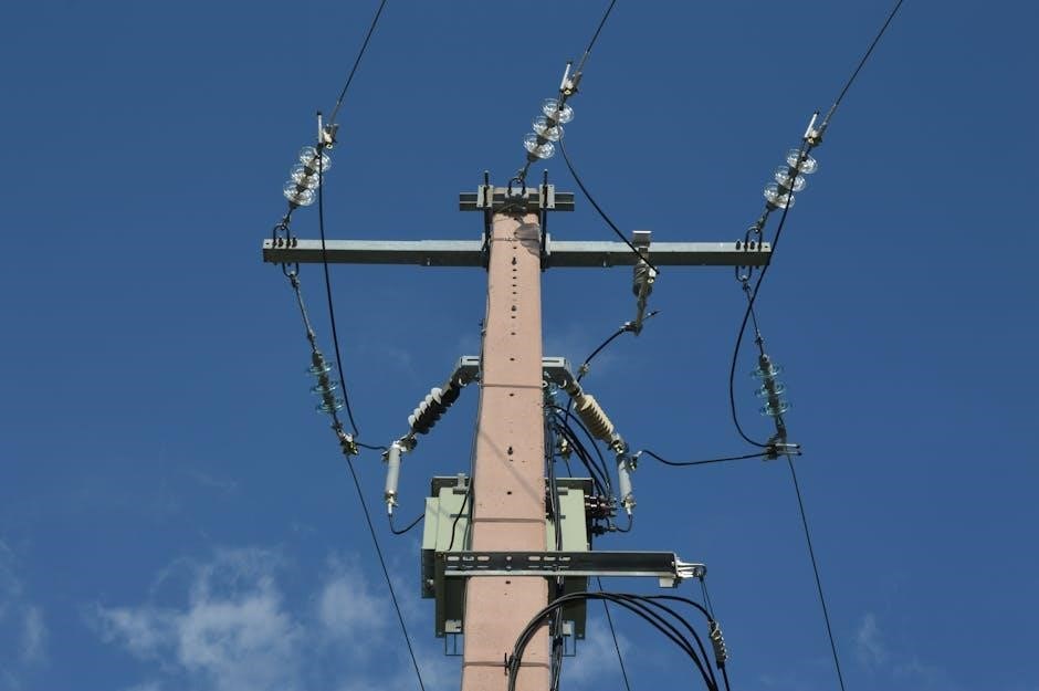
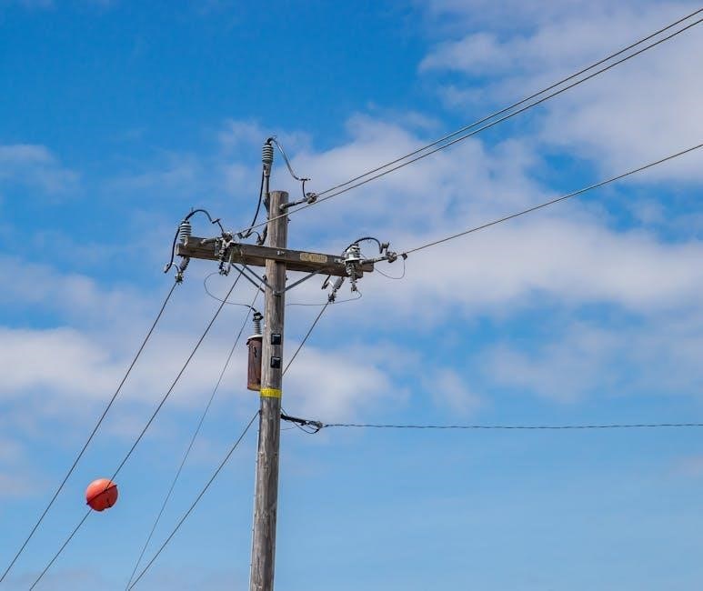
Transformer wiring is a fundamental aspect of electrical systems, ensuring efficient power transfer. Proper techniques, safety, and understanding diagrams are crucial for reliable connections and configurations.
1.1 What is a Transformer?
A transformer is an electrical device that transfers power between circuits through electromagnetic induction. It consists of primary and secondary windings wrapped around a common core. The primary winding receives the input voltage, while the secondary winding delivers the transformed voltage. Transformers are used to step up or step down voltage levels, ensuring efficient power transmission and compatibility with various electrical systems. The core, typically made of laminated steel, enhances magnetic coupling between the windings. Proper wiring and configuration are critical for safe and efficient operation, making transformers essential in industrial, residential, and renewable energy applications.
1.2 Importance of Proper Transformer Wiring
Proper transformer wiring is crucial for ensuring efficient and safe electrical power transfer. Incorrect wiring can lead to overheating, reduced efficiency, or even complete system failure. It is essential to follow the manufacturer’s wiring diagram and adhere to local electrical codes. Proper connections ensure minimal energy loss, reduce the risk of electrical hazards, and maintain system reliability. Additionally, correct wiring prevents premature wear and tear on the transformer, extending its lifespan. Always prioritize safety by using appropriate tools and techniques, and consult a licensed electrician if unsure. Regular inspections and adherence to standards are vital for optimal performance and longevity.

Understanding Transformer Wiring Diagrams
Transformer wiring diagrams are essential for guiding the installation and troubleshooting of transformer connections. They provide a visual representation of windings, terminals, and connections, ensuring proper configuration and safety.
2.1 Types of Transformer Wiring Diagrams
Transformer wiring diagrams are categorized into several types, including single-phase and three-phase configurations. Single-phase diagrams typically illustrate basic step-up or step-down setups, while three-phase diagrams detail more complex connections, such as delta and wye configurations. Additionally, diagrams may vary based on transformer applications, like buck-boost or multi-tap transformers. These visual guides ensure correct terminal connections, polarity, and grounding, which are critical for safe and efficient operation. Understanding the differences and purposes of each diagram type is essential for proper installation and troubleshooting. Accurate diagrams help prevent electrical hazards, ensuring systems operate within specified voltage and current ratings.
2.2 Reading Single-Phase Transformer Diagrams
Reading a single-phase transformer diagram involves identifying the primary and secondary windings, understanding polarity markings, and recognizing connections. The primary winding receives the input AC power, while the secondary provides the output. Polarity markings, like dots, indicate winding direction to ensure correct connections. The diagram may show step-up or step-down configurations, guiding voltage transformation. Terminals are labeled, such as H1 and H2 for primary, and X1 and X2 for secondary. Taps on the secondary allow multiple voltage outputs. Grounding points ensure safety, and fuses or circuit breakers protect against overcurrent. Symbols denote ratings, and notes provide installation and safety instructions. Methodically interpreting these elements ensures safe and efficient transformer operation.
2.3 Reading Three-Phase Transformer Diagrams
Reading three-phase transformer diagrams requires understanding the connections and configurations for both primary and secondary windings. These diagrams typically depict wye (Y) or delta (Δ) configurations, with vector relationships shown. Polarity markings and terminal labels (e.g., H1, H2, H3 for primary; X1, X2, X3 for secondary) guide proper connections. Tap settings are often included for voltage adjustments. Grounding points are highlighted for safety. The diagram may also show phase sequences and internal connections. Understanding these elements ensures correct installation and operation, especially in industrial settings where precise voltage and phase matching are critical for machinery and power distribution systems.

Transformer Installation Requirements
Transformer installation requires selecting the right model, preparing the site, setting appropriate taps, and ensuring proper grounding. Compliance with local codes and safety standards is essential for safe operation.
3.1 Choosing the Right Transformer for Your Needs
Selecting the appropriate transformer involves evaluating voltage requirements, power ratings, and phase configurations. Ensure the transformer’s capacity matches the load to prevent overheating or inefficiency. Consider single-phase for residential use and three-phase for industrial applications. Verify compatibility with existing systems and compliance with safety standards. Proper selection ensures reliable performance, efficiency, and longevity of the transformer. Always consult specifications and seek professional advice if uncertain.
3.2 Site Preparation for Transformer Installation
Proper site preparation is essential for safe and efficient transformer installation. Ensure the area is level, dry, and free from debris. Check for adequate drainage to prevent water accumulation. Keep the surrounding area clear of flammable materials and ensure proper ventilation. Verify that the site meets local electrical codes and manufacturer guidelines. Ensure accessibility for installation and future maintenance. Install necessary mounting platforms or pads as required. Provide adequate lighting for the installation process. Conduct a final inspection of the site before proceeding with transformer placement to ensure all safety and regulatory standards are met.
3.3 Understanding Transformer Tap Settings
Transformer tap settings are crucial for adjusting voltage ratios to meet specific load requirements. Taps are connection points on the transformer’s windings, allowing flexibility in voltage adjustment. Proper tap selection ensures efficient operation and prevents overloading. Always consult the wiring diagram for tap configuration guidance. Adjusting taps requires de-energizing the transformer to avoid risks. Use appropriate tools and follow manufacturer instructions. Tap settings are vital for maintaining optimal voltage levels, ensuring reliable performance, and extending transformer lifespan. Misconfigurations can lead to inefficiency or equipment damage, making accurate tap selection essential for safe and effective transformer operation.
3.4 Grounding Requirements for Transformers
Proper grounding is essential for transformer safety and performance. Grounding ensures electrical safety by providing a path for fault currents to safely dissipate. Connect the transformer’s ground terminal to an earth point, following local electrical codes. Use appropriately sized grounding conductors to minimize resistance; Ensure all metal parts are bonded to the grounding system to prevent voltage differences. Regularly inspect grounding connections for corrosion or damage. Improper grounding can lead to equipment damage, fire hazards, or electrical shocks. Always consult the transformer’s wiring diagram for specific grounding instructions. Adherence to grounding requirements is critical for reliable and safe transformer operation.
Step-by-Step Transformer Wiring Guide
A systematic approach ensures safe and efficient transformer wiring. Start by gathering tools, understand the wiring diagram, and proceed with connecting primary and secondary windings securely.
4.1 Gathering Necessary Tools and Equipment
To ensure a smooth transformer wiring process, gather essential tools and equipment. These include insulated screwdrivers, wire cutters, strippers, and a multimeter for voltage and resistance measurements. Safety gear like gloves and goggles is crucial. Ensure you have the correct gauge wire for your transformer’s specifications. A wiring diagram specific to your transformer model is indispensable for accurate connections. Organize all components beforehand to avoid delays. Double-check that all tools are in good condition and suitable for the voltage levels involved. Having a well-prepared setup minimizes errors and ensures compliance with safety standards, making the wiring process efficient and secure.
4.2 Connecting the Primary Winding
Connecting the primary winding requires careful attention to the transformer’s wiring diagram. Identify the primary terminals, usually marked as “H1” and “H2,” and ensure they are compatible with your voltage supply. Use a multimeter to verify the resistance of the primary winding. Connect the input power supply lines to these terminals, ensuring proper polarity. Secure the connections tightly to avoid loose wires. Always de-energize the circuit before starting work. Use insulated tools to prevent electrical shock. Double-check the wiring diagram to confirm the correct configuration for your transformer type, whether it’s single-phase or three-phase. Proper connections ensure safe and efficient operation.
4.3 Connecting the Secondary Winding
Connecting the secondary winding involves linking it to the desired load. Identify the secondary terminals, typically labeled “X1” and “X2,” and ensure they match your required voltage output. Use a multimeter to measure the secondary winding’s resistance to confirm proper connections. Attach the load wires to these terminals, maintaining correct polarity to prevent damage. For multi-tap transformers, select the appropriate tap to meet your voltage needs. Secure all connections firmly to avoid short circuits. Always refer to the wiring diagram for specific configurations. Ensure the secondary circuit is properly insulated and grounded. Turn on the power gradually to verify output voltage stability.
4.4 Ensuring Proper Grounding Connections
Proper grounding is essential for safety and efficient transformer operation. Identify the grounding terminal on the transformer, usually marked as “G” or “Earth.” Connect this terminal to the system’s grounding point, such as a grounding bar or earth rod. Use a wire of appropriate gauge to ensure low resistance. Verify that all connections are secure and free from insulation damage. Test the grounding circuit with a multimeter to ensure continuity and low resistance. Proper grounding protects against voltage spikes, ensures safe operation, and prevents equipment damage. Always follow local electrical codes and standards for grounding requirements to maintain system integrity and user safety.
Safety Considerations in Transformer Wiring
Always de-energize circuits before wiring. Use proper tools and follow safety codes to avoid electrical hazards. Ensure grounding and insulation are correct to prevent shocks and fires.
5.1 Electrical Safety Precautions
When working with transformer wiring, always de-energize the circuit before starting. Use properly insulated tools and wear protective gear to prevent electrical shocks. Ensure all connections are secure and meet local codes. Never overload the transformer, as this can cause overheating or failure. Proper grounding is essential to prevent voltage spikes and ensure safe operation. Keep the work area clean and dry to avoid short circuits. Always refer to the manufacturer’s guidelines for specific safety recommendations. Failure to follow these precautions can result in serious injury or equipment damage. Safety should always be the top priority when handling transformer wiring.
5.2 Avoiding Common Wiring Mistakes
Common transformer wiring mistakes include incorrect phase connections and mismatched voltage ratings. Ensure the primary and secondary windings are connected as per the diagram. Mixing up taps can lead to improper voltage levels, potentially damaging equipment. Overlooking grounding requirements is another frequent error, which can compromise safety. Always double-check the transformer’s polarity and wiring configuration before energizing. Misaligning the transformer’s capacity with the load can cause inefficiency or overheating. Refer to the manufacturer’s specifications to avoid such issues. Proper planning and careful execution are key to preventing these mistakes and ensuring reliable operation.
5.3 Understanding Transformer Ratings and Limits
Understanding transformer ratings and limits is crucial for safe and efficient operation. Key ratings include voltage, current, and power capacity, which must align with the connected load. Exceeding these limits can cause overheating or failure. Insulation withstand voltage and fire retardancy are also critical for safety. Always refer to the manufacturer’s specifications to ensure compliance. Properly matching the transformer’s capacity to the load prevents inefficiency and potential damage. Adhering to these ratings ensures reliable performance and longevity of the transformer, avoiding premature wear or catastrophic failure. This step is essential for maintaining electrical integrity and safety in any system;

Troubleshooting Transformer Wiring Issues
Identify common wiring problems, test transformer windings, and repair faulty connections to ensure optimal performance and safety. Regular checks help prevent unexpected failures and ensure reliability.
6.1 Identifying Common Wiring Problems
Common transformer wiring issues include short circuits, open circuits, and incorrect tap settings. These problems often arise from faulty connections or misinterpretation of wiring diagrams. Overheating, buzzing, or voltage drops can signal underlying issues. Using tools like multimeters to test resistance and voltage helps diagnose problems. Visual inspections can reveal loose wires or damaged insulation. Incorrect phase connections in three-phase systems can cause imbalance and inefficiency. Addressing these issues promptly ensures safe and efficient transformer operation, preventing potential damage or safety hazards. Regular maintenance and adherence to wiring standards are key to minimizing such problems and ensuring reliable performance. Early detection saves time and resources.
6.2 Testing Transformer Windings
Testing transformer windings is essential to ensure their integrity and functionality. Use a multimeter to measure resistance, checking for shorts or open circuits. Insulation resistance testing with a megohmmeter verifies insulation quality. Compare primary and secondary winding resistance to the manufacturer’s specifications. Measure turns ratio using a turns ratio tester to confirm proper connections. Perform these tests with the transformer de-energized and disconnected from the circuit. Regular testing helps detect issues early, preventing failures. Always follow safety protocols and refer to the wiring diagram for accurate test points. Proper testing ensures reliable operation and extends the lifespan of the transformer, avoiding costly repairs.
6.3 Repairing Faulty Connections
Repairing faulty transformer connections requires careful identification and correction of issues. Start by disconnecting power and verifying the circuit is safe. Use a multimeter to test for shorts, opens, or resistance imbalances. Inspect wiring and terminals for damage, corrosion, or loose connections. Clean or replace faulty components, ensuring proper torque on terminals. Refer to the wiring diagram to trace and repair specific faults. After repairs, retest connections to confirm functionality. Always follow safety protocols and manufacturer guidelines. If unsure, consult a licensed electrician to avoid further damage or safety risks. Proper repairs ensure reliable operation and prevent future failures.

Advanced Transformer Wiring Configurations
Explore advanced transformer wiring setups, including buck-boost, multi-tap, and phase-shifting configurations, to optimize power systems for specific industrial or high-capacity applications.
7.1 Buck-Boost Transformer Configurations
Buck-boost transformers are versatile devices used to adjust voltage levels by a fixed percentage; They can either “buck” (lower) or “boost” (raise) the input voltage, typically by 5-20%. These configurations are ideal for applications where small voltage adjustments are necessary. Buck-boost transformers are commonly used in industrial machinery and renewable energy systems. Proper wiring involves connecting the primary and secondary windings according to the desired voltage change. Always refer to the manufacturer’s wiring diagram to ensure correct connections and safe operation. This configuration is efficient and cost-effective for minor voltage adjustments without requiring a full transformer replacement.
7.2 Multi-Tap Transformer Wiring
Multi-tap transformers offer flexibility by providing multiple voltage taps, allowing users to select from different voltage levels. This configuration is ideal for applications requiring adjustable outputs. Proper wiring involves connecting the correct taps based on the desired voltage. Always consult the manufacturer’s wiring diagram to ensure accurate connections. Multi-tap transformers are commonly used in industrial machinery and renewable energy systems. They allow for efficient voltage adjustments without the need for multiple transformers. Ensure all connections are secure and follow safety guidelines to prevent overloading or voltage imbalances. This setup is cost-effective and space-saving for systems with varying voltage requirements.
7.3 Phase-Shifting Transformer Configurations
Phase-shifting transformers are specialized configurations used to adjust the phase relationship between voltage sources. They are commonly employed in industrial applications to control power flow and manage reactive power. These configurations involve specific wiring techniques to achieve the desired phase shift, often using vector diagrams to guide connections. Proper setup ensures minimal losses and optimal performance. Phase-shifting transformers are particularly useful in systems requiring precise voltage regulation and power factor correction. Always refer to the manufacturer’s specifications and wiring diagrams for accurate implementation. This configuration is essential for maintaining stability in complex electrical networks and ensuring efficient energy distribution.
Transformer Wiring for Specific Applications
Transformer wiring varies across industrial machinery, residential systems, and renewable energy setups, requiring customized configurations to meet unique voltage and power demands efficiently and safely.
8.1 Wiring Transformers for Industrial Machinery
Transformer wiring for industrial machinery requires precise configurations to handle high power demands. Typically, industrial transformers are used to step down high voltage to safe, usable levels for equipment. They are essential for powering motors, drives, and large-scale machinery. Configurations vary between single-phase and three-phase setups, depending on the application. Proper grounding and insulation are critical to ensure safety and efficiency. Industrial transformers often include features like overload protection and thermal monitoring. Compliance with local electrical codes and standards is mandatory. Regular maintenance and testing are recommended to prevent downtime and ensure reliable operation in demanding industrial environments.
8.2 Transformer Wiring for Residential Systems
Transformer wiring in residential systems primarily involves step-down configurations to deliver safe, low-voltage power to households. Typically, residential transformers convert high-voltage AC power to 120/240V for home use. Wiring must adhere to local electrical codes, ensuring proper grounding and insulation to prevent hazards. Installation involves connecting the primary winding to the incoming power lines and the secondary winding to the home’s electrical panel. Regular inspections and maintenance are crucial to maintain efficiency and safety. Proper wiring ensures reliable power distribution, protecting appliances and ensuring compliance with safety standards. Always consult certified electricians for residential transformer wiring to avoid risks and ensure compliance.
8.3 Transformer Wiring for Renewable Energy Systems
Transformer wiring for renewable energy systems, such as solar or wind power, involves configuring step-up or step-down transformers to match the system’s voltage requirements. These systems often require specialized wiring to handle variable energy outputs and ensure efficient power conversion. Proper grounding and surge protection are critical to safeguard against voltage spikes and ensure system reliability. Transformers in renewable energy setups must be selected based on their compatibility with DC-AC inverters and the specific demands of the installation. Regular maintenance and adherence to international standards are essential to optimize performance and safety in these environmentally friendly power solutions.

Compliance and Standards in Transformer Wiring
Compliance with local and international electrical standards ensures safety and efficiency in transformer wiring. Adherence to regulations like UL and IEC is crucial for reliable and legal installations.
9.1 Understanding Local Electrical Codes
Local electrical codes provide specific guidelines for transformer wiring, ensuring compliance with safety standards. These codes vary by region and must be followed to avoid legal issues and ensure safe installations. Understanding these codes is essential for electricians to meet regulatory requirements. Proper adherence helps prevent hazards and guarantees efficient power distribution. Always consult local authorities for the most updated regulations before starting any transformer wiring project to ensure full compliance and safety.
9.2 Compliance with International Standards
Compliance with international standards ensures transformer wiring meets global safety, efficiency, and performance criteria. Organizations like IEEE and IEC set these standards, covering transformer design, testing, and safety. Adhering to these guidelines ensures compatibility and reliability across markets. Compliance reduces the risk of electrical failures and guarantees products meet global market demands. Always refer to the latest standards, such as IEEE C57 or IEC 60076, for specific requirements. This ensures your transformer wiring aligns with universally accepted practices, fostering safety and operational excellence worldwide.
9.3 Documentation and Certification Requirements
Proper documentation and certification are essential for transformer wiring projects. Maintain detailed records of wiring diagrams, test reports, and installation logs. Certifications from recognized bodies ensure compliance with safety and performance standards. Ensure all documentation includes transformer ratings, tap settings, and grounding details. Keep records of personnel training and qualification for wiring tasks. Certifications like UL or IEC markings verify product safety and reliability. Organize documentation for easy access during inspections or audits. Regular updates ensure compliance with evolving standards. Proper documentation and certification are critical for legal, safety, and operational requirements, providing a clear audit trail for transformer wiring projects.
Ensure all connections are secure, and verify transformer ratings match load requirements. Conduct final inspections and tests to confirm proper operation, safety, and efficiency before system activation.
10.1 Summary of Key Wiring Principles
Proper transformer wiring involves understanding diagrams, ensuring correct primary and secondary connections, and maintaining safe grounding. Verify transformer ratings match load requirements to prevent overheating or failure. Always follow local electrical codes and manufacturer guidelines for secure and efficient connections. Regular inspections and testing are essential to ensure reliability and safety. Proper tools and equipment are necessary for precise installations. Avoid common mistakes like incorrect tap settings or polarity issues. Ensure all connections are tight and insulated to prevent short circuits. Adhere to grounding requirements for optimal performance and safety. Document all steps for future reference and compliance checks.
10.2 Final Inspection and Testing
A thorough inspection ensures all connections are secure and correctly configured. Verify primary and secondary wiring matches the diagram, and tap settings align with voltage requirements. Test voltage levels using a multimeter to confirm proper operation. Check for any signs of damage or wear on wires and connections. Ensure grounding is correctly installed and functioning. Perform insulation resistance tests to verify integrity. Use a megohmmeter to check for short circuits or ground faults. Always follow safety protocols when testing live systems. Document test results for future reference. Ensure compliance with local electrical codes and manufacturer recommendations for safe and efficient transformer operation.
10.3 Maintaining Transformer Efficiency
Regular inspections and tests are essential for maintaining transformer efficiency. Check for signs of wear, such as overheating or insulation damage, and address them promptly. Verify that tap settings are correct for the load requirements. Ensure all connections are tight and free from corrosion. Perform routine cleaning and replace any damaged components. Use a megohmmeter to test insulation resistance annually. Monitor voltage levels to ensure they remain within specified ranges. Proper grounding and cooling systems must be maintained to prevent overheating. Follow manufacturer guidelines for lubrication and filter replacements if applicable. Efficient maintenance ensures optimal performance, safety, and longevity of the transformer.
